For over 70 years, Metro Hydraulic Jack Company, a third-generation, family-owned and operated business, has been providing industrial hydraulic parts and equipment services to commercial, automotive, marine, refuse, and construction industries.
More About Our CompanyCatalog
- Shopping Cart (0)
- Quotes (0)
- Express Ordering
- All CategoriesAll Categories
- ValvesValves
- SPX Power Team ValvesSPX Power Team Valves
- 4 Way Valves4 Way Valves
- Item # 9632
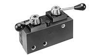
Item # 9632, Twin 4 - Way / 3- Position (Tandem Center) Manual Valve
Price
-
$2,749.88Qty.
- Add To Cart
- Request Quote
Application: Multistrand, double acting stressing jacks with an auxiliary seating cylinder.
Actuation: Dual lever operated, detent positioned.
Used on these pumps: PA17 (These pumps may have reduced first flow stage characteristics due to internal valve restrictions.), PA46 (These pumps may have reduced first flow stage characteristics due to internal valve restrictions.), PA55, PE17(These pumps may have reduced first flow stage characteristics due tomore internal valve restrictions.), PE21 (These pumps may have reduced first flow stage characteristics due to internal valve restrictions.), PE30, PE46 (These pumps may have reduced first flow stage characteristics due to internal valve restrictions.), PE55, PE84, PE120, PE200, PE400, PG30(These pumps may have reduced first flow stage characteristics due to internal valve restrictions.), PG55, PG120, PG400, PQ60 and PQ120 series. (These pumps may have reduced first flow stage characteristics due to internal valve restrictions.)
To prevent sudden, uncontrolled descent of a load as it is being lowered, use a No. 9596 Load Lowering Valve or No. 9720 Counter Balance Valve in conjunction with the directional valve used in your application. Conversion kit 251528 must be used when mounting any of the valves on PA17 or PE17 pumps. less
Valve Type |
N/A Post Tensioning |
Actuation |
N/A Dual Lever Operated, Detent Positioned. |
Pressure Rating |
N/A 10000 psi |
Max. Flow Rate |
N/A 5 GPM |
Port Size |
N/A 3/8 inches |
Function |
N/A Special Advance/Return |
Operation |
N/A Manual |
Application |
N/A Single Acting Cylinder Double Acting Cylinder |
Used On Pumps |
N/A PE17 PE21 PE30 PE46 PE55 PE84 PE120 PQ60 PQ120 PA55 PA17 PA46 PE200 PE400 PG30 PG55 PG120 PG400 |
Weight |
N/A 13.6 lbs. |
Ship Weight |
N/A 14.3 lbs. |
|
N/A
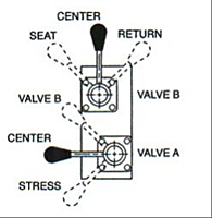
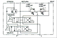
1. With valves “A” and “B” in center position, pump is started; cable is inserted into stressing tool. |

 Search


